|
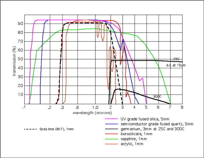
One of the sensors I would like to add to the weather station is an UV sensor. It would provide local information about the current UV intensity. One sensors that sparked my interest was the SI1145 Digital UV Index / IR / Visible Light Sensor from adafruit.com (product id: 1777). 10 USD excluding shipping make this an affordable sensor and it has a calibrated UV sensing algorithm that can calculate the UV index. This is very convenient because the UV index is the same format that Weather Underground accepts when you want to upload sensor data. So why haven't I installed one yet? Waterproofing UV SensorsAlmost all hobbyist UV sensors are made available as a circuit board without a waterproof enclosure. So you are probably thinking, why not put it in a clear plastic container and add it to the weather station? Lets have a look at the properties of UV light. For the UV index we are interested in wavelengths between 295 and 325 nm. The main property of interest is the optical transmission of UV light through different materials. We are looking for a materials that lets the most amount of UV light through for the most accurate results by the UV sensor. Most materials block UV light to a certain degree and become an UV filter. Thats why 3$ sunglasses almost work as well as 100$ sunglasses. To identify suitable materials we will use the following graph. The graph plots various materials and their transmission properties. The transmission properties vary by wavelength. The graph uses microns as the unit for wavelength. 300nm equals 0.3 microns. So that is the vertical axis we will look at. Straight away we can identify that the materials acrylic and germanium are unsuitable since they don't let through any UV at a wavelength of 0.3 microns.
I will list possible candidates and their optical transmission in %:
So know we know which materials we have to look for to use as a waterproof barrier for the UV sensor. But are there useable pieces available and are they affordable? For this I use eBay. I will be looking for round pieces with a minimum thickness of 3mm and a minimum diameter of 18mm. These are the results (prices are material + shipping).
Even though Borosilicate is more affordable I would try out the fused silica and do some tests to find out if the optical transmission corresponds to that of the graph. So it will be a 35 NZD investment for the sensor cover. The sensor is 10USD. Converting it to NZD and shipping to New Zealand will bring up the price probably to that of around 30 NZD. So now the cost of adding an UV sensor is already at 75 NZD. That leaves us with designing and making of the actual waterproof case that will hold the sensor with the glass shielding still to be added to the price. So I won't be adding a UV sensor at this moment because of the cost. When there is a strong demand or a sponsor I might change my mind. But until then the current implemented range of sensors will have to make do.
7 Comments
I decided to write a post about the NZ Rural Broadband Initiative (RBI) and my concerns around it. I have attended only one public forum run by the Blenheim council for the people in Marlborough. This provided me with some insight on the progress in Marlborough and I had the opportunity to voice some of my concerns around RBI. Unfortunately I haven't been able to go to any follow up meetings and I am unable to find meeting minutes of these meetings. First a short explanation of what the RBI is supposed to achieve. Currently there are many places in New Zealand with no or limited access to the internet. Some places don't have a wired connection (phone line, broadband or fibre) to their property and cell phone reception can be scares or non existent. The big telecom providers aren't interested in spending a lot of money to install a new cell phone tower or dig up the road to put a cable in if it is only going to be utilised by a few people. That's where the NZ RBI comes in. First to identify the locations with no or poor connections to the internet. Second, connect these households up by subsidising Wireless Internet Service Providers (WISPS). A WISP will install an Wi-Fi antenna onto your house and connect it to their own privately owned and operated infrastructure. Similar to the system I build but on a larger scale. The price and throughput depends on the WISP. My personal concernsSince the RBI has been announced it seems like every month a new WISP comes into existence in the hope to make some money. Although I understand that it is a smart idea to find a hole in the market, my worries lie with the quality of work that is going to be delivered by inexperienced people or when short cuts are made. Putting something up that sort of works is easy. Designing a system that is robust, scalable, efficient, within regulations etc. is not. Whenever I see a new WISP advertising for the Marlborough region I try to do a basic background check. I will leave it up to the readers to do their own research. So all these WISP are most likely using similar equipment and especially frequencies. Most likely around the 5.8gHz. My biggest worry is frequency management. First of all, are the WISP going to be forced to use licensed spectrum as not to interfere with existing community broadband radio links? At the moment the amateur spectrum for long range PtP links is very narrow and already overused and in some places illegally broadcasted on. If WISP will use the same spectrum it is going to be one huge frequency jamming war with the result that nobody will have a decent throughput. So frequencies and their bandwidth will need to be regulated and commercial operators should not be allowed to use parts of the unlicensed spectrum. Many WISP will create an infrastructure with repeater stations on hill tops to create a line of sight to their customers and other repeater stations. How are we going to protect a repeater site from being sabotaged by a competitor. I don't necessarily mean damage to equipment but the installation of another WISP equipment right next to yours, interfering or blocking transmissions. SummaryHere is a quick summary of my concerns from the previous section:
ConclusionThe RBI created a hole in the market which a lot of people want to take advantage of. If council/government doesn't put the right regulations in place the RBI will result into a war between WISPs and existing community networks. I suggest the following:
Tips for potential customersHere are some tips if you are considering a WISP for broadband to your household.
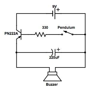
A few years ago I came across an article of a boy that connected an inexpensive earthquake alarm to an Arduino with an ethernet shield and had it post an alert on twitter every time an earthquake was detected. In this post We will look at a couple of ways we can connect the Quake Alarm to a microprocessor and discuss the positives and negatives of each method. The alarm used is called "Quake Alarm™". I decided not to upload a photo of the device with the components visible to prevent any complications with the company that makes them. Here is a description of how the device works: "the quake alarm™ is designed to provide instant warning of seismic activity by detecting the "p" wave (compression wave) of an earthquake, which travels faster than the more destructive "s" wave (shear wave). the quake alarm™ saves valuable seconds by removing the guesswork in earthquake detection. it is capable of detecting large earthquakes that occur hundreds of miles away and can detect moderate to minor earthquakes for many miles around your local area." Lets have a look at the circuit and its components.
Note: I am not sure about the original resistor value because I already made some modifications to my device. The circuit looks like this. When there is an earthquake, the pendulum starts to swing and touches the sides and creates a closed contact. A current will flow between the base and the emitter and allows a charge to flow between collector and emitter turning on the buzzer. The capacitor smooths out the voltage spikes caused by the fast closing and opening of the switch(pendulum). So how can we modify this circuit so we can read it out with a microprocessor (i will use the word AVR for the rest of the post). The following examples will take into are based on the assumption that the microprocessor uses 5V logic. I will use an Arduino Uno as a reference AVR. Some examples will need to be slightly changed when using 3.3V logic. 1. Reading analog valuesThe easiest circuit is to strip it to remove the battery and connect the AVR to the power connector. The voltage is supplied by the AVR on the positive terminal and the negative terminal is connected to one the the analog capable pins on the AVR. On an Arduino Uno those are pins A0 to A5. Poll the analog pin and when an earthquake causes the pendulum to close the circuit a voltage drop will cause the analog reading to change. Have your program do something when the analog reading goes beyond a certain value. Positives
Negatives
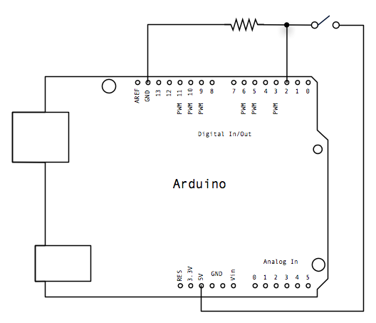
2. Simple switch with Interrupts (digital)If we want to make sure that an earthquake doesn't go unnoticed we can use a hardware interrupt to catch any seismic activity. When an interrupt is triggered it stops execution of the code that was running at the time and executes the code that handles the interrupt. When the interrupt is taken care of it continues execution of the paused program. For this example we only use the pendulum from the Quake alarm and use a 10K pull-down resistor. When the pendulum is open (no earthquake) there is no connection between the two legs of the pushbutton, so the pin is connected to ground (through the pull-down resistor) and we read a LOW. When the pendulum is closed (there is an earthquake), it makes a connection between its two legs, connecting the pin to 5 volts, so that we read a HIGH. For interrupts to work on an Arduino Uno connect either to in 2 or 3. for more info about interrupts on Arduino's click here. Tip: Add software debouncing to the code for when an earthquake triggers and interrupt to prevent it from registering as a series of earthquakes. Positives:
Negatives:
Whats next?Although there are plenty more ways to connect up a Quake Alarm to an AVR you are either going to create an analog or digital signal and both of these are discussed above.
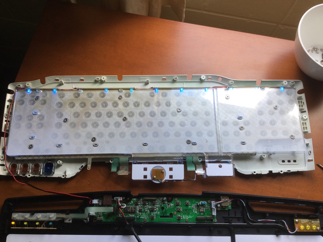
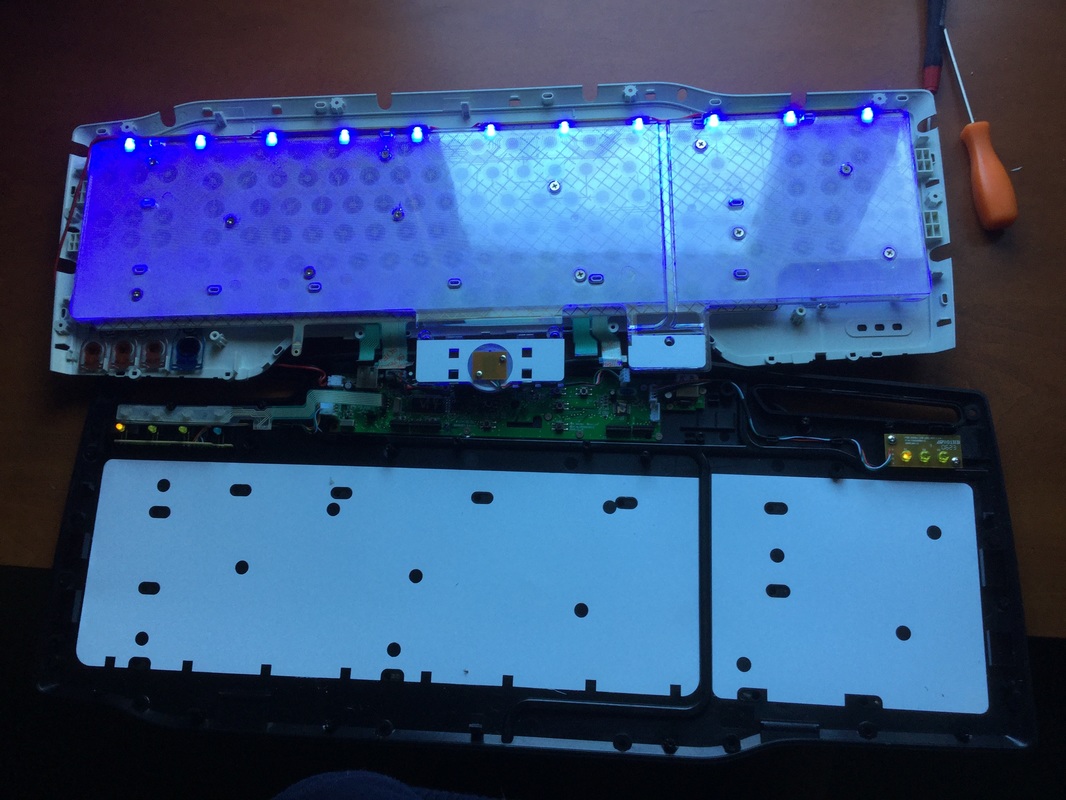
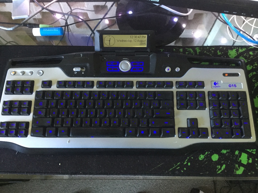
Now you have a way of capturing earthquakes you have plenty of possible applications. Add a real time clock and a SD card and you can log when earthquakes could be detected at your location. Add an ethernet shield or WiFi capabilities and you can for example send a twitter message when an earthquake is detected. etc. et. For some time now my Logitech G15 V1 gaming keyboard backlight started to flicker and was a lot dimmer than it used to be. I felt it was a good time to do some trouble shooting and see if I could fix the problem. Disassembly took a bit of time. There are lost of screws and a couple of hidden clips that you have to carefully disengage if you don't want to break them off. Then there are a couple of ribbon connectors which you have to unplug. These are really fragile and one wrong movement and you can throw the keyboard away. After disassembly this is what I found. Notice that the third LED from the left doesn't work. After a quick look in my electronic supplies I found my collection of 3mm blue diffused LEDs left over from my 8x8x8 LED cube. I decided to not just swap out the damaged LED but all of them. They where all getting old and could cause an uneven dispersion of light because of the difference in the LEDs. What a difference. I think that even though the LEDs are wired in parallel that the moment one LED dies all of them somehow are affected. Hopefully with all the LEDs replaced this problem won't reoccur any time soon. One of the hardest part of the assembly is connecting the ribbon cable for the LCD screen.. But as you can see everything works as expected and I can finally see the letters on the keyboard again. And after these repairs the flickering of the backlight has disappeared too.
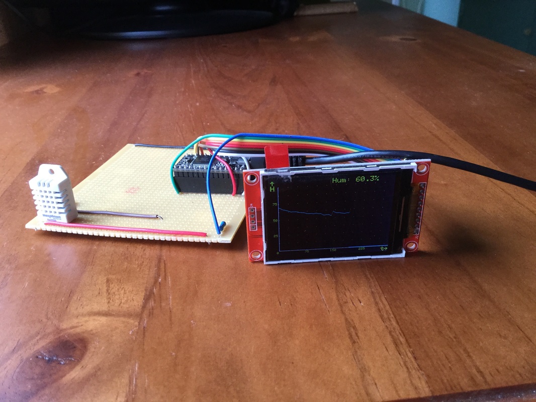
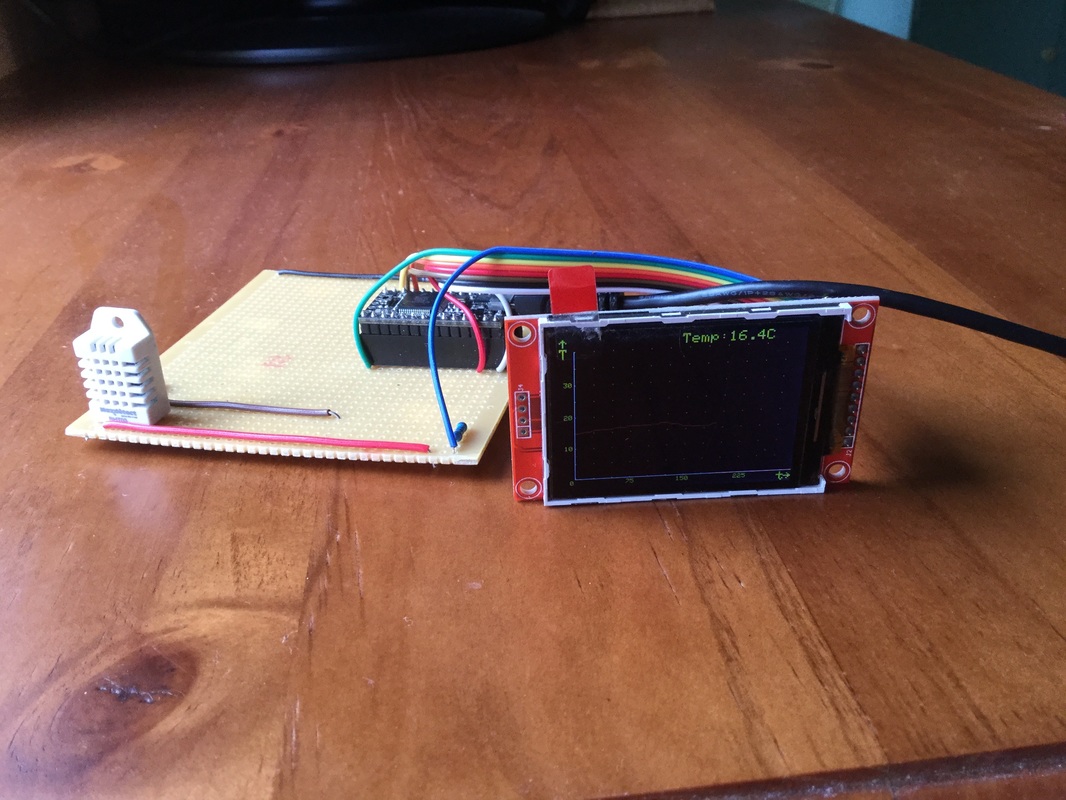
When I moved back to Wellington I was curious about the living conditions of my new flat. The two big issues with New Zealand houses are the humidity and temperature. I recently purchased a 320x240 color TFT display (ILI9341) of eBay which has an optimised library for Teensy microprocessors. So I quickly connected up the following components:
I ported the code from a previous project (click here) to save some time coding. My current monitor stores 300 temperature and humidity measurements. It stores a measurement every minute so I can view them in the form of a line graph and see what happened in the flat for the last five hours. The most recent measurement is displayed in the top right of the display. Healthy humidity levels are between 40% and 60%. This is what I have observed so far. When the dehumidifier is turned off, humidity ranges between 75% and 80% (I always have some windows slightly open). When the dehumidifier is turned on it drops to around 55% before the dehumidifier switches off and switches back on when it rises above 60%. The dehumidifier is set to 50% but because it isn't in an optimum location it measures different results then at the location of my sensor. Temperature drops to a stable 13 °C. The apartment is partly dug out of the bank. So back wall creates a form of heat sink. Unfortunately this is not insulated at all. So when a heat source is turned of, temperatures fall back to 13 °C really fast. And as most old houses the windows are single glazing. Possible improvements are:
Post a comment if you are interested in the code. |
AuthorGeorge Timmermans, Research Toolmaker, Software Engineer and Tinkerer Archives
March 2024
Categories |
Proudly powered by Weebly

 RSS Feed