Arduino Solar Swimming Pool Controller
Why the need for a swimming pool controller? The swimming pool (see banner) is located on a property that is not connected to the main grid. Electricity is generated through a hydro turbine and solar panels. Excess power is stored in a 48VDC battery bank. The hydro generator generates around 800 Watts continuously in winter and 300 in summer as long as there is enough water. Because of the limited amount of electricity available the swimming pool system (around 350 Watts) can't run 24/7. The water in the pool can't be heated with electric heaters for the very same reason. Therefor we rely on a solar heating. Water runs through black matts which warms up in the sun before going back into the pool. Water is not allowed to go through if it will result in cooling down the pool when it is not wanted. For example at night or on a cold cloudy day.
Solution
|
The basic functionality consist out of comparing two temperatures and determine if the valve that lets water through the solar panels should be open or closed. Currently the pump is controlled through a relay by the Arduino and through a relay on the Inverter. The second relay prevents the pump from being enabled when the batteries are low.
|
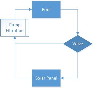
Circuit diagram - Water
|
The Circuit
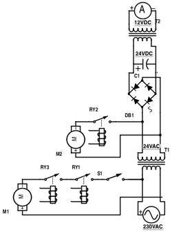
Circuit diagram - Power*
|
* Symbols might not be correct and are used to depict other components.
Several devices operated on different voltages. For example:
Following is an explanation of the parts in the circuit diagram:
|
Code
|
The code is available on github, click here.
The program reads various sensors on a fixed interval. When the required amount of samples have been collected the average of the sampled data is calculated. The two important sets of data that determine if the valve for the solar panels should be opened are the indoor swimming pool temperature and the outdoor solar panel temperature. The valve is controlled by comparing the two temperatures and open or close the valve depending on predetermined setpoints. Because the swimming pool and the solar panel vary in temperature constantly the setpoints can be described as:
|
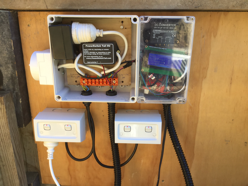
Current prototype
|
Why two setpoints?
By creating a gap between the setpoints we eliminate the problem that occurs if the temperature slightly fluctuates over and under a single setpoint. With a single setpoint this fluctuation would result in opening and closes the valve multiple times in a short amount of time. This would drastically reduce the lifespan of the mechanical relays.
Why all those extra sensor readings in the code?
This is an experimental system. Before I came up with the above program I collected data from multiple sensors and tried to identify a reliable pattern that I could use for my program. The sensors used and data stored on a SD card so that the system can be tweaked and the results can be compared. The environmental data I collect is:
- Swimming pool temperature
- Solar panel temperature
- Air temperature inside pool house
- Humidity inside pool house
- Light intensity inside pool house
Inverter Settings
The relay wire for the pump is connected to a normally open contact from one of the auxiliary relays in the inverter. When the battery voltage goes above 54VDC the relay closes and when the voltage drops below 52VDC the relays opens up again. Because it is part of the Arduino controlled circuit the pump can only run when the following conditions are met:
- Batteries are above 54VDC
- Temperature of solar panels is higher then that of the swimming pool.