|
I decided it was about time to see if I could repair a pop up headlight for a 1990 Mazda Eunos Roadster (Miata). The part in question is a plastic part that had worn out and causes a wobbly headlight. The Genuine Mazda Part Number is: NA01-51-SA5 but consist out of parts I don't really need to replace. The cost of the replacement part is around 25 NZD + 25 NZD shipping. I took the damaged part from the car, measured the critical dimensions and created a CAD model in Autodesk Inventor Pro 2016 that I recently acquired with a three year license. I found this website with the necessary coefficients to add PLA to the material database. PLA is the main material I use for 3D printing. The part clips over a ball joint so I use the stress analysis in Inventor to see how it would behave. See picture below. 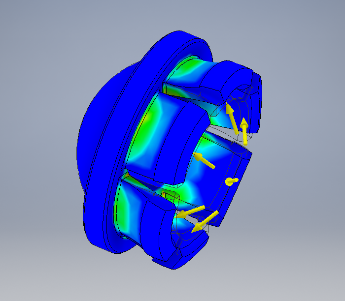 Unfortunately it doesn't reflect the weakness between layers created by Fused Deposition Modeling (FDM) used by my 3D printer. I tried a couple of iterations but every time I tried to snap the newly printed part on the ball joint some of the clips would break off. I wish I had some Nylon filament to try out. Nylon is used for 3D printing very strong parts and has great strength between layers. In the end I decided to order a genuine replacement part. I prefer not to have the headlight close on me while driving at night. Other PartsBelow is a picture of a clip I designed in SketchUp over a year ago. It is a replacement for the clip that holds the rod that you use to keep the hood of the car up while doing maintenance in the engine bay. I know it seems pretty insignificant but I am surprised it is still holding up to temperatures and vibrations within the engine bay. Yuo can download the source file and 3D print file here. 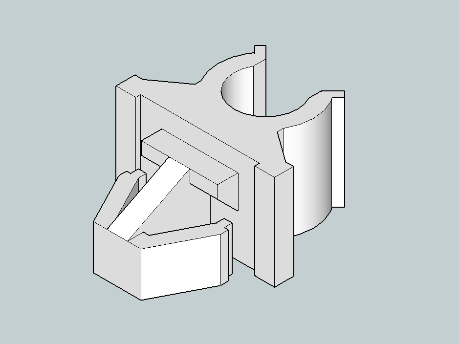 Another part that resulted in a failure was a plastic part that connected to drivers-side suns visor to the car. The original had broken in two halves and i looked like a previous owner of the car might had taken it apart and had made matters worse. A working is important for the Warrant Of Fitness for the car. Again I took the critical dimensions and made a simple replacement for testing. It looked promising to start of with until a very nice summers day. The car is a racing green colour with a black soft top. The temperature of the body of the car and inside of the car had risen to such an extend that the PLA had become a little soft and the weight of the sun visor deformed it. I repaired the original with a composite glue but if it breaks again I might try printing it in ABS. UpdateI sold the car in 2018 with the clip I 3d printed in PLA in 2015 in it! So depending on what it is and where it is installed it is possible. A lot off better materials are on the market today for 3d printing.
2 Comments
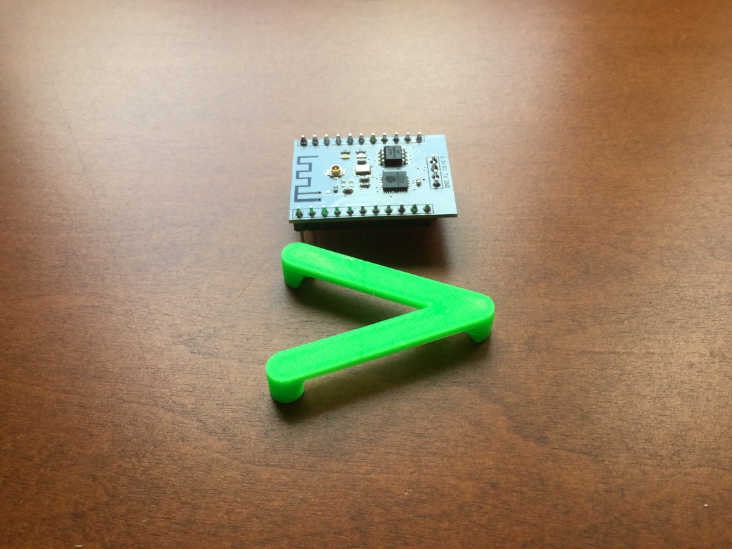
My student license for Solidworks expired and for the time being I will be using SketchUp for designing some models for 3D printing. By default SketchUp isn't very useful for 3D printing, But by installing two extensions we will be able to output 'solid' STL's. Solid Inspector²Solid Inspector² is an extension that will analyse your model, point out possible errors and give you the option to automatically repair the model for you. In SketchUp it is very easy to miss these errors if you analyse the model manually. You can download Solid Inspector² here. SketchUp STLBy default SketchUp doesn't provide support for the import and export of .STL files. Support is added by installing SketchUp STL which you can download here. 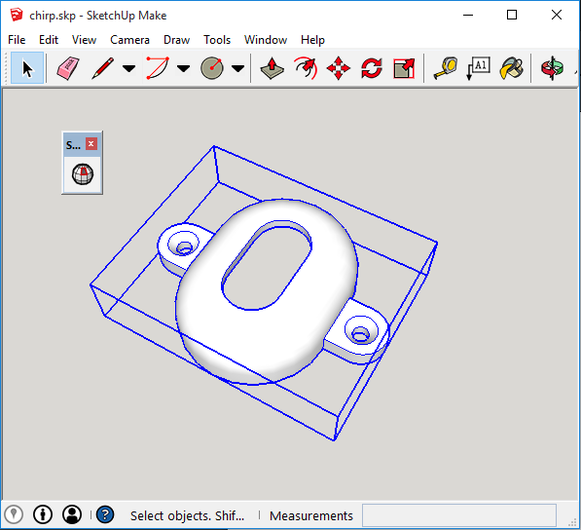 My WorkflowI start SketchUp and use the template "3D Printing - Millimeters". When you finished designing your model, select the whole model, right click and click "Make Component". Give it a sensible name and click "Create". While your component is selected (blue box around it) click the Solid Inspector² to analyse it for any errors. Resolve errors if you encounter them. otherwise go File->Export STL. Enable "Export selected geometry only.", Export unit: Millimeters, File format: Binary and click "export".
Choose a location to save your STL. Before printing I tend do a "print preview" with my slicer and look at all the layers if I can spot any funny travel moves that shouldn't be there. If there are you will have to go back to your SketchUp model and manually check what might be causing it. Remove all unnecessary lines form your model. Try View->Face Style->Wireframe to see if you have any lines within your model that you can get rid off. If you need to edit your component, right click the component and click "Edit Component". After you are done right click next to the component and click "Close Component".
Unfortunately they are not responding to my email and message to remove it from their website. My license clearly states non commercial and on the website that sells these there is not a single reference to the original source or attribution.
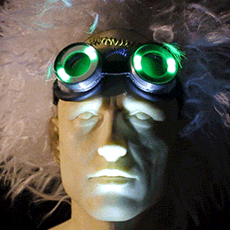
While checking one of the open source electronics websites I came across instructions on how to make some costume goggles with individual addressable LEDs.
But just following some assembly instructions and uploading some code isn't a challenge for me. So I decided to make my own advanced version of these goggles. 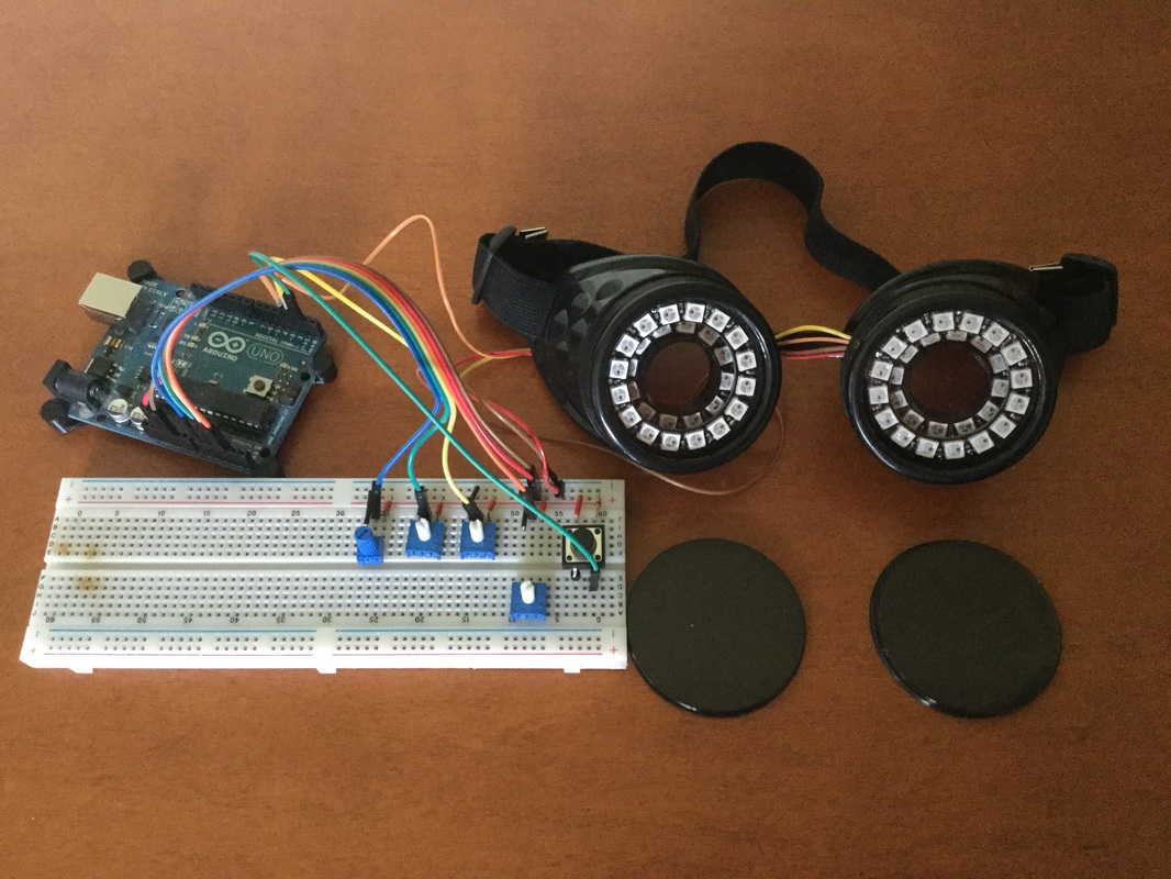 Here are my goggles in the current prototyping stage. The main difference is that I don't have one LED ring per eye but two. As you can see the goggles house a 24 LED and 16 LED ring. To accomplish this I designed and 3D printed an insert that hold the LED rings neatly in place but still provide access to the soldering pads. I also designed it in such away that it prevents light leaking to the sides. So they goggles could be safely worn even when the LEDs are on. Manual ControlsI thought about adding Bluetooth capabilities but since I don't own a smartphone and don't want to walk around with an iPad during parties I opted for manual controls. At the moment I use three potentiometers and a button.
The code is non blocking and uses a state machine for the animations. The button uses an interrupt but it doesn't have to be. By using timed events and a state machine instead of delays it is easier to create steady frame rates, react faster to buttons and dials and future proofs it for hardware like bluetooth where we need to be able to detect incoming data. 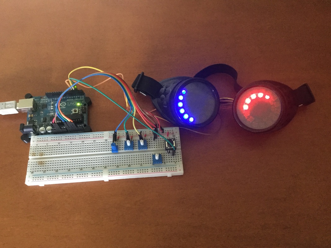 The code is really scalable. It is just a matter of adding a new animation to the switch case. Hardware ChoicesThe idea is that the finished project will be fully contained around the goggles. This will include the micro controller, manual controls and battery. The LEDs require 5V logic. Therefor I ordered something similar to an Arduino Micro for the final version of the goggles. It has a small form factor and removes the need for logic level shifting. I will be on the lookout for some cooler looking potentiometers and buttons.
It will also require designing and 3d printing an enclosure that will contain the micro processor, batteries and controls. But that will be a post for another time. |
AuthorGeorge Timmermans, Research Toolmaker, Software Engineer and Tinkerer 
Archives
March 2024
Categories |


 RSS Feed