|
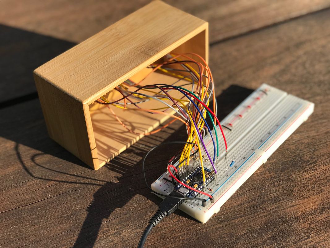
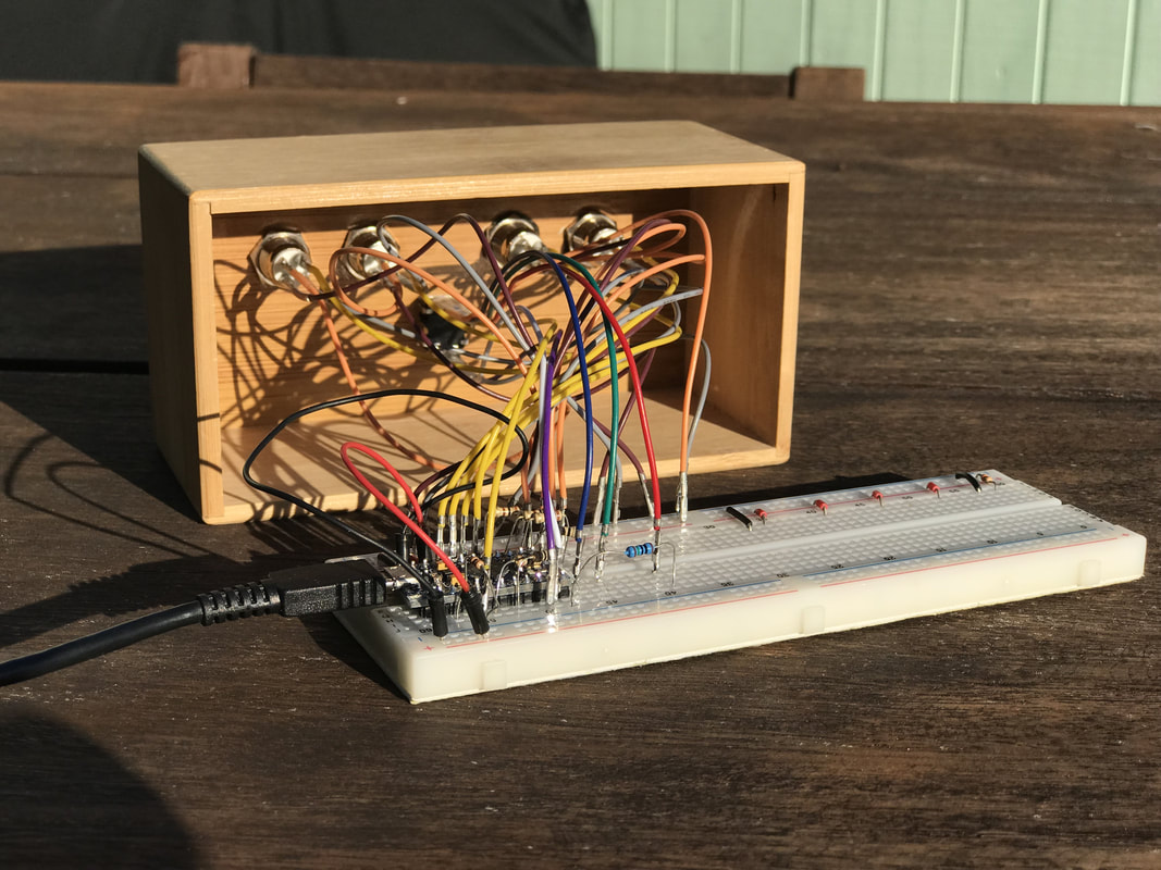
As you might have noticed I thoroughly enjoy building embedded projects. An Arduino starter kit got me interested in software development and that let me to a bachelors in information technology and my career as a software developer, Every time when my project has past the initial breadboard prototype phase and I want to create a permanent circuit i hit the same hurdle. I use plenty of IO pins and a lot of the inputs and outputs require either a input voltage or reference to ground or both, Most boards only provide one or two, maybe three of these. So I designed a simple breakout board to solve this issue. 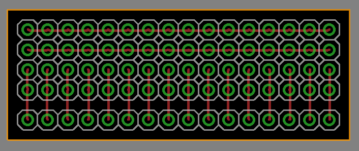 In the photo above the bottom row is where you would connect it to your microprocessor. The next two rows are connected to these pins and provides the ability to add pull/down resistors. If you want to use servo connectors then the next row should be bridged to your VCC pin so you create a VCC rail and the top rail should be bridged to GND to create a reference to ground rail. I attached some photos of a recent project where I used two boards to breakout all the pins for an Arduino pro micro. I also upgraded my raspberry Pi photobooth with one of these breakout boards. I am very happy with the result. I used EAGLE to design the PBS's and https://oshpark.com/ to manufacture them. oshpark provides a EAGLE plugin that will help generate the files for manufacturing to their liking. And that's a very big help for an amateur digital PCB design like me. Taking your prototype to complete project has never been so easy. See attached files if you want to make your own.
0 Comments
A while ago I ordered some LED flickering candles. This particular set comes with build in rechargeable batteries and a charging tray. It comes with a European style 7.5v power supply which is no good to me without a travel adapter. Instead I wanted something simple. No adapters, or buying a new power supply. Opening the charging tray revealed a simple circuit containing a 5V regulator. That's convenient. This makes it well suited for charging via an USB cable. While checking the circuit I discovered the current limiting resistor for the LED to be very large. 1K ohm, while 210 ohm would have been enough in it's original configuration. I think it was done to reduce the brightness of the LED. With my conversion to 5V I swapped out the resistor for a 100 ohm resistor, which results in 20mAh going through the LED. It's now nice and bright. Because the batteries don't have any markings on them and there is no overcharge protection anywhere It is not recommended to leave them on charge for a very long time. At least I have now a convenient charging solution. Parts have been trickling in and I found something that will make a decent permanent enclosure. I had the misfortune to receive a partially defective rotary encoder which has been replaced. In the photos below all the connections are made with the appropriate current limiting resistors so I could writing the code for all the buttons and LED animations. A video of it working is still to come. I attempted to digitally design a circuit board and have it manufactured. At the time of typing this the manufacturers website is unavailable so I can not check the status of my order. Hopefully more about that next time. Back to the controller. So far it consist out of:
Up next is permanently wiring things up and 3d printing a bracket to hold the microprocessor in place. And some tidying up of the code so it will be in a good enough state to publish. It has been a while since I build something worth sharing. I have been updating existing 3D designs but I have to calibrate my 3D printer before I can print and share them. In the meantime a new project came up. I recently bought a new keyboard to replace my 10 year old Logitech G15. I now enjoy the use of a Logitech Pro TKL mechanical keyboard. It comes with individual programmable RGB (what doesn't these days) keys and several re-programmable function keys. I quickly discovered how badly I miss a feature that my old keyboard had and the new one doesn't (unless you set up macros or use function keys). What I really miss is the volume wheel and easy access media control buttons. I have set up macros for now but I took the opportunity to solve the problem by building my own USB peripheral device. The prototype in the video below does volume up, down and mute by using a (RG) rotary encoder with build in switch that is read by an Arduino pro micro which sends keyboard commands to the computer. My future version will incorporate play/pause, next, previous and stop buttons. and the rotary encoder will be a RGB for improved visual clues. It will take a while for more parts to arrive, But while I wait I can start designing a case to hold it all the buttons and electronics. I can't even remember if the passenger side door lock ever worked when you inserted the key. It wasn't until my recent road trip I discovered how annoying it was not being able to lock the passenger side door from the outside. With my recent interest in lock-picking and having seen many videos of locks been taken apart, I thought it was about time to tackle this challenging problem. First was the matter of getting the lock out of the door. Luckily somebody made some really good instructions (see here). Most people seem to replace the locks on the car, but I was all up for restoring it. After carefully taking the lock core out of the bible (housing) I could properly check what was wrong. NOTE: be careful not to loose the tiny ball bearing used to index the resting position of the core in the bible when taking the two apart. I am now pretty sure that somewhere in in the last 27 years someone has tried to open the lock by jamming a screwdriver in it and forcefully trying to turn the core. The effect was that now the first wafer was permanently stuck and thus preventing the opening or closing of the door by key. After taking all the wafers out, make sure you remember the order, first up was the cleaning of the bible, core and wafers. The wafers can be polished with very fine sandpaper. You will discover a number on each wafer, which you could write done in case you want a new key made. When attempting to put the wafers back I found out that the first one still didn't move freely. The forceful attempt to open the lock had caused a burr in the core. After sanding that off and removing all other damage I could find it was time to carefully assemble the lock again. And behold, I have a working lock again. Getting it installed in the door is another challenge. Just take your time and follow the instructions in reverse order. |
AuthorGeorge Timmermans, Research Toolmaker, Software Engineer and Tinkerer 
Archives
March 2024
Categories |
||


 RSS Feed