|
I have been busy ordering some of the parts required for this project. Since some of the stuff is ordered from early it will take a while for them to be delivered. Here is a list of some of the components I will be using, subject to change:
Seer the (rough) circuit diagram below on how the flash will be connected though the MOSFET module. The same circuit will also be used for the light in the dome button and using it as a status indicator. Only difference is that it will use a different GPIO pin. 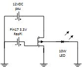 Ground must be from a common source which if you use the PSU from the list above will meet that requirement. The LED is connected on the 12VDC power circuit and trough the MOSFET which will act as a normally open switch. The raspberry Pi will provide a 3.3VDC signal when a photo will be taken which will "close" the switch and the turn on the LED. When I have all the actual hardware I will show how to connect everything up. And I will share the changes required to the open source software I am using to get the flash working. Finished Photo booth
1 Comment
Jeremy
5/10/2016 09:20:35 pm
Awesome George! I'm ordering all the same parts now. Great blog too! Your comment will be posted after it is approved.
Leave a Reply. |
AuthorGeorge Timmermans, Research Toolmaker, Software Engineer and Tinkerer 
Archives
March 2024
Categories |
 RSS Feed